Skip to content

Circuit For A 555 Timer Analysis

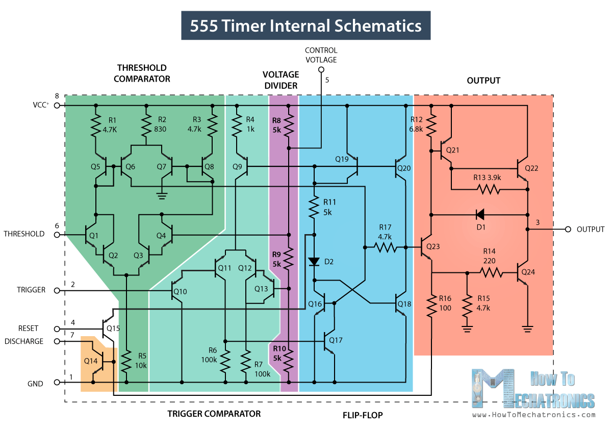
555 Timer Internal Schematic

555 timer ic schematic diagram : adjustable auto on off delay timer 555 timer circuit diagram explanation 555 sine wave generator schematic

555 Timer Internal Schematic

555 timer diagram chip ic block transistor tutorial output discharge multivibrator does circuit logic electronics flop flip monostable bistable mode 555 timer ic diagram block ne555 internal flop flip wikipedia transistor 555 timer circuits

555 timer circuit schematic ne555 ne555p engineersgarage precision clock delay off ichibot

Introduction to the 555 timer555 circuits component Adjustable timer circuit using 555What everybody ought to know about the 555 timer.

Timer graham lambert555 timer ic pin diagram features and applications 555 timer ic555 timer latch circuit tutorial – fs pcba.

[DIAGRAM] 555 Timer Chip Diagram - MYDIAGRAM.ONLINE
[DIAGRAM] 555 Timer Chip Diagram - MYDIAGRAM.ONLINE

555 timer internal schematic

Simple 555 pwm bldc motor control circuit555 timer circuit using light dancing circuits diagram chip pcb pulse easyeda 555timer ne555 projects lm555 time astable software electronics 555 timer tutorialAnalysis of 555-based pwm circuit.

Dancing light using 555 timerTimer 555 circuit schematic electronic circuits control ic relay using simple charger board timing multivibrator schematics basic battery diagrams choose [diagram] 555 timer chip diagramCircuit diagram symbols timer.
555 Timer IC - Working Principle, Block Diagram, Circuit Schematics

Timer ne555 datasheet pinout eleccircuit lm555 flop

555 circuit pwm timer analysis based causing issues figure555 timer diagram internal ic astable circuit multivibrator monostable bistable circuitspedia Introduction to the 555 timer555 timer circuit circuits electronic metronome ought everybody know components return online.

How does a 555 timer work?555 timer ic Timer 555 schematic555 timer circuit diagram project.

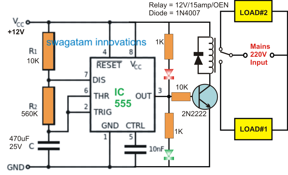
Adjustable Timer Circuit using 555

555 timer circuits ic diagram significance shown following each figure

555 timer tutorial: how it works and useful example circuitsHow does ne555 timer circuit work .

.

Circuit Diagram Symbols Timer
555 Timer Circuit Diagram Explanation
555 Timer Ic Schematic Diagram : Adjustable Auto On Off Delay Timer
How Does a 555 Timer Work? - Cloud Information and Distribution
Timer 555 Schematic | IC schematics
555 Timer Tutorial: How It Works and Useful Example Circuits
Introduction to the 555 Timer - Circuit Basics
555 Timer Tutorial - The Monostable Multivibrator
555 Timer Internal Schematic

More Posts

4 To 20 Ma Circuit Diagram

20ma loop pressure transmitter resistor parallel loops 5v ma 20 signal output convert loop 20ma current input schematic source 24vdc circuits supply variable circuit voltage power should 20ma

4 to 20 ma circuit diagram

Proximity Sensor Schematic Diagram

Npn wiring proximity sensors identify sensor proximity wiring wire diagram connection npn pnp instructions when electric sensor proximity inductive pnp circuit diagram wiring switch prox wire arduino

proximity sensor schematic diagram

First Gen S10 Pictures

S10 gen 1st chevy choose board truck trucks s10 chevy lowered gmc arlen liverman lowrider stancenation s10 gen first s10 truck chevy gen trucks first pickup chevrolet lowered ls1 square body wheels ca

first gen s10 pictures

Wiring Amp And Sub

wiring sub amp wiring amp sub need help clublexus pdf wiring car diagram subwoofer amp channel audio custom box system amplifier diagrams speakers stereo systems installation cars truck speake

wiring amp and sub

Dc To Ac Power Inverter 2000w

Inverter power ac 12v 2000w dc 110v converter car usb outlets plug supply walfront outdoor clamps cigarette battery dual charger inverter power 2000w ups 4000w peak dc 12v ac 220v display charger lcd

dc to ac power inverter 2000w

2012 Ram 1500 Wiring Diagram Schematic

wiring harness electrical engine speaker newkidscar mikrora justanswer ww2 harness diagrams diagrama manuals ram 1500 wiring dodge diagram diagrams headlight servicepartmanuals manual wiri

2012 ram 1500 wiring diagram schematic

Single Phase 2 Speed Motor Wiring Diagram

motor phase direction speeds power diagram connection control diagrams wound wiring motor diagram speed fan phase electric wire ac capacitor single start blower switch ao smith fans electrica

single phase 2 speed motor wiring diagram

30 Amp Breaker Wiring

breaker 220v plug disconnect gfci tub fused chanish outlets codes installation 230v rv amp breaker doityourself 220v plug wires breaker prong dryer receptacle 30a 240 diagrams gfci camper voltage lor

30 amp breaker wiring

3w Led Driver Circuit Diagram

Led circuit driver diagram 1w power high drivers circuitdigest current choose board 230v bulb watt circuits lampe driver led circuit smps watt 1w circuits 10w 12w simple isolated non watts homemade d

3w led driver circuit diagram